Thermal imaging has always fascinated me. The ability to “see” heat opens up a whole new dimension of perception, making it a powerful tool for diagnosing electrical faults, detecting insulation leaks, and even exploring the world at night. So, I decided to build my own DIY thermal camera using a Raspberry Pi, a thermal sensor, and a custom circuit board.
Materials
Required
- Raspberry Pi Zero 2W
- 8GB SD Card
- Standard Raspberry Pi camera module (I used v1.3)
- Ribbon cable for Pi camera connection
- 2.4-inch LCD display (SPI interface)
PCB Assembly
- Custom PCB or protoboard for wiring (Schematics on Github)
- MLX90640 thermal camera module
- USB-C TP4056 5V 1A Charging Module
- 2x20 2.54mm Male + Female Pin Header
- 3x Pushbuttons
- 8-pin 2.54mm Angled Pin Header
- SPDT 4mm Slide Switch
- 3D-printed enclosure
Additional Hardware
- 3.7v Lithium Polymer Battery*
- 4x M3x8mm screws
- 4x M3x15mm screws
- 2x M2x20mm screws
- 2x M2 nuts
- M3 Heat inserts
Tools
- Soldering iron
- 3D printer + filament
- Multimeter for testing
- Wire cutters & strippers
- Hot glue gun
*Although the battery is not strictly required, and the entire device can be powered via the USB-C port, the PCB design calls for it, and it massively increases the versatility of the device. I used a 652540 650mAh battery, as it was the largest I could feasibly fit into the design. It lasts anywhere from 45 minutes to 3 hours, depending on usage.
Like always, .step and all other files will be provided on this project’s Github Page so you can print and create your own!
The Build
This project revolves around two key components: a standard camera module for visible light and a thermal imaging sensor to detect infrared radiation.
Component Explanation

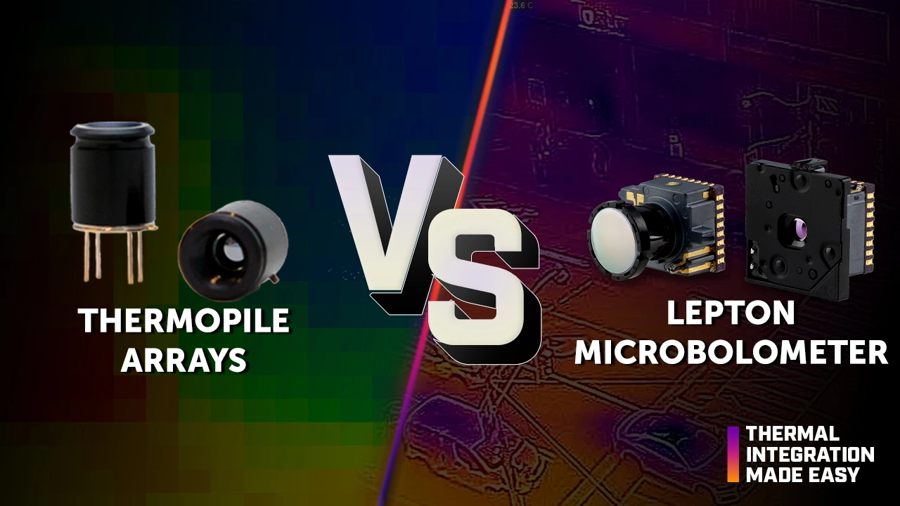
The thermal camera module captures infrared radiation and converts it into a temperature map. I used the MLX90640, which offers a resolution of 32x24 pixels. This is relatively low by visual camera standards, but enough for basic thermal imaging. This is an effect of the type of sensor used. Thermopile sensors (the technology used to make the MLX90640) are cheaper to produce than the alternative microbolometer technology used by some more advanced sensors on the market, such as the ones produced by Teledyne FLIR, which have resolutions as high as 1024x768. However, those can cost as much as $40,000. Even their ‘consumer grade’ sensors with resolutions of 160x120 still cost $200-$300 at the time of writing this blog, more than the cost of the entire camera.
The Raspberry Pi camera provides a normal visible-light image, which I blend with the thermal data to create an easy-to-interpret overlay. In my case, I’m using the simple v1.3 Raspberry Pi camera, with a max video resolution of 1080p@30fps. However, my LCD display resolution is only 240x320, so the camera’s full sensor isn’t being fully leveraged, contributing to extended battery life.
The Raspberry Pi Zero acts as the brain of the system, collecting and processing the data, then displaying the output on the LCD screen. All data is collected through the 40-pin header, with the exception of the Pi camera, which is interfaced through the mini CSI connector at the bottom of the Raspberry Pi.
PCB Design

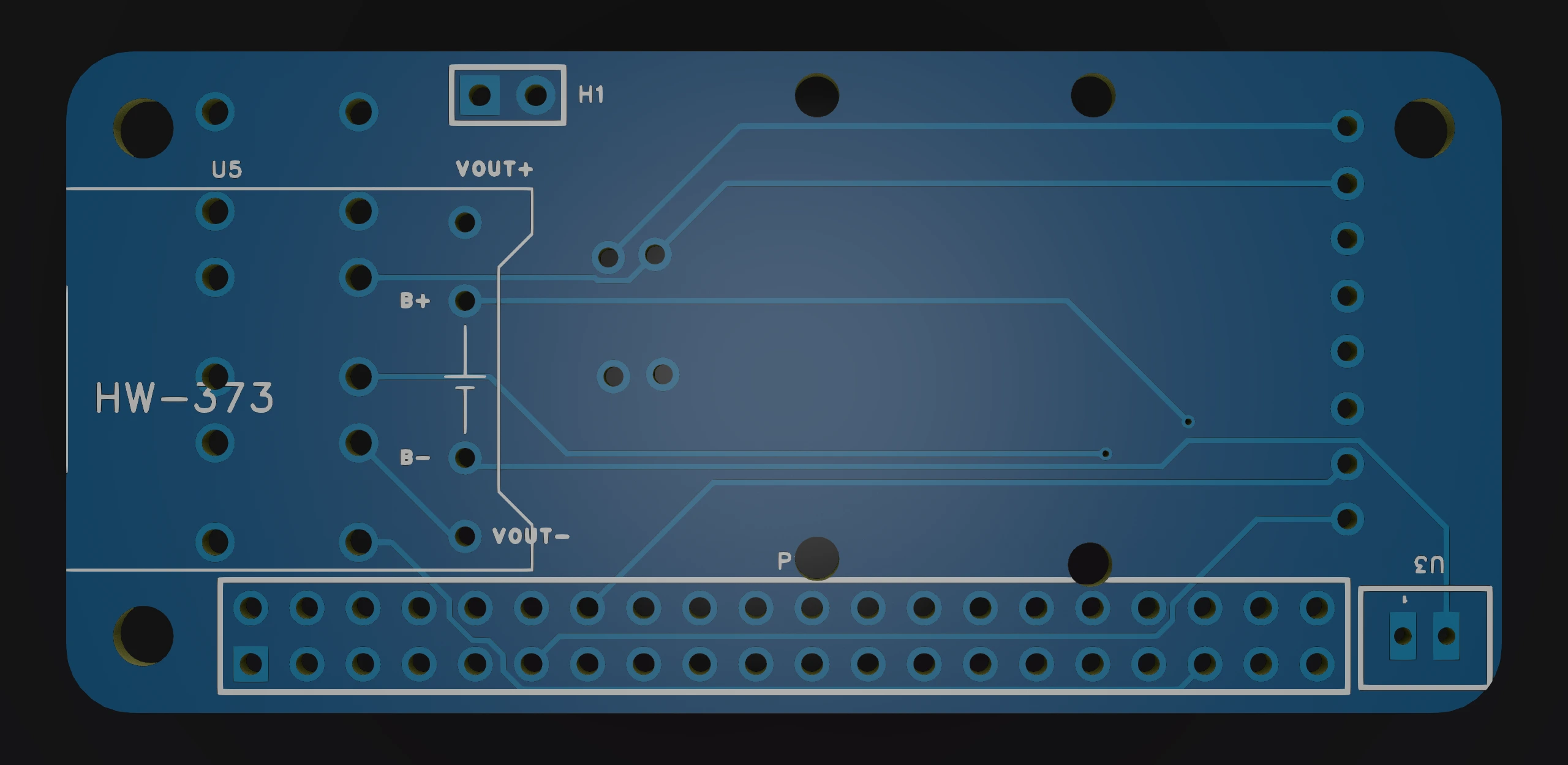
One of the unique parts of this build that I am particularly proud of was the custom circuit board I designed and had manufactured for this project. It interfaces with the Raspberry Pi Zero using the 40-pin GPIO header, and has the following functionality:
- An I2C breakout for the MLX90640 thermal camera sensor
- Support for up to 3x programmable buttons
- A USB-C battery charging module for power
- A physical power switch
- Mounting holes for the Pi camera
- A battery port to power the entire project
I designed this PCB using EasyEDA, a free and easy to use online EDA software. Next, after multiple design revisions and DRM checks, I used JLCPCB’s PCB manufacturing service to have my custom circuit board brought to life. Their manufacturing and shipping process took about 2 weeks, and soon I was left with a custom circuit board at my front door.

Upon testing, everything seemed to go to plan. So, after extensive continuity checks, I soldered the most expensive component to the circuit board first; the MLX90640 sensor. After painstakingly ensuring that polarity was correct, I soldered it into place, and to my relief, when plugged into the Raspberry Pi Zero’s GPIO header, not only did the thermal sensor not blow up or burn out, but it was immediately recognized by the i2cdetect -y 1 command at the correct I2C address, 0x33.
With the most stressful part of the project behind me, I soldered on the rest of the components, and after ensuring their functionality I moved onto writing the code for this project.
System Architecture
The project involves multiple processes running simultaneously:
- Capturing images from the Raspberry Pi camera
- Separately capturing thermal data from the MLX90640 sensor
- Blending the two images together
- Displaying the final thermal-augmented image in real time
To achieve this, I implemented multi-threading in Python using the threading library to ensure smooth performance despite the Raspberry Pi’s limited resources. This massively sped up the performance of the camera, and was genuinely the only way that this project was able to be usable as an actual tool.
The Software
The core of this project is the Python script that handles image capture, processing, and display. Although the code was not the main focus of the project, this was my first successful foray into python multithreading, and it turned out incredibly successful. Here are some of the main features of the software:
- Threaded Image Processing: The camera and thermal sensor run in separate threads to ensure fast, asynchronous updates.
- Image Blending: Using PIL (Python Imaging Library), the visible-light image is blended with the thermal overlay.
- Real-time Display: The final processed image is shown on the LCD screen at around 30 FPS.
- Programmable buttons: 3 dedicated buttons control 3 core functions:
- Pausing the camera + thermal sensor stream to save battery life
- Saving a photo to the SD card for further processing
- A proper camera shutdown sequence for storage when not in use
All of the code is contained in a single python file. Here’s a look at the core display logic:
def display_image():
    global camera_image, thermal_image, blended_image
    while True:
        with image_lock:
            if camera_image is not None and thermal_image is not None:
                # Convert images to RGBA format
                camera_rgba = camera_image.convert("RGBA")
                thermal_rgba = thermal_image.convert("RGBA")

                # Blend the images together
                blended_image = Image.blend(camera_rgba, thermal_rgba, 0.75)

                # Show the final output on the LCD display
                disp.ShowImage(blended_image.convert("RGB"))
            elif camera_image is not None:
                # Fallback to normal camera feed if no thermal data is available
                disp.ShowImage(camera_image.convert("RGB"))

        time.sleep(0.033)  # Maintain ~30 FPS display refresh rate
The image_lock ensures that the thermal and camera images are processed without conflicts, making the system more stable. Without this, I frequently ran into image lag and desyncing issues.
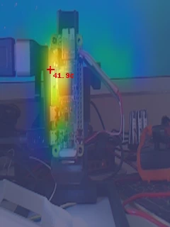
Not shown in the core logic is the code that locates hotspots in the image and displays their temperature, a subtle but very useful feature to help diagnose overheating issues on computers and other electronics.
An interesting thing to note is the framerate difference between the thermal sensor and the Pi camera. The pi camera did not have any bottlenecks; in fact, for the camera, the limiting factor for framerate was the speed of the SPI interface, where I was able to squeeze out ~30fps when writing full frames to the display. However, the thermal sensor was only stable up to 4fps. Worse still, not every frame came back properly. The MLX90640 has an integrated IC in the sensor that handles the communication of the sensor with the computer. The interface of choice was I2C, and although this made for an extremely easy setup, I2C isn’t exactly the fastest communication protocol around. This, combined with the knowledge that often the MLX90640 isn’t able to return the sensor data in time, led to an interesting design challenge. However, I wasn’t willing to sacrifice framerate just yet. Instead of capping the entire display to 4fps, I used the threading library as mentioned above.
The code would repeatedly saturate the SPI connection to the LCD with updated visible-light camera data, to provide visual context to the user. Additionally, it would continue to overlay the last-received thermal data from the MLX90640. Then, when new thermal data was received from the sensor, from a different thread as the camera, the updated sensor data would be combined together. This allowed me to maintain a much higher framerate, albeit with the thermal data lagging behind. However, this tradeoff made the device far more useable.
3D Printing & Enclosure Design


A critical part of making this a handheld device was designing a compact, ergonomic enclosure. I used Onshape to design a custom case that:
- Holds the Raspberry Pi + circuit board securely to the front of the camera
- Mount the display firmly to the back of the camera
- Provides a slot to charge the battery using a USB-C cable
I designed the case to be assembled using M3 screws with heat-set inserts for durability, and used a slip-fit securing mechanism aided by hot glue to attach the ON/OFF switch firmly in place.
Conclusion
This project is one that I am most proud of in my workshop. It works very well, for a fraction of the price of a commercial FLIR camera, and I learned a tremendous amount along the way.
Results & Lessons Learned

After assembling and debugging, I finally had a working DIY thermal camera! The blended images were clear, and the device successfully detected hotspots, as well as the wide range of temperatures within 0.1 C°.
What I Would Improve
-
Higher-Resolution Thermal Sensor - The MLX90640 works well, but a higher-resolution sensor like the FLIR Lepton 3.5 would produce much sharper images, and behave much more like a professional, market-ready product.
-
Faster refresh rate - The MLX90640 has a rated refresh rate of up to 64 FPS, but even online I wasn’t able to see an example of anyone getting more than 16 FPS consistently out of the sensor. Worse still, I was only able to achieve 4 FPS consistently, and attempting to increase the framerate led to instability and initialization errors.
-
Form Factor - Currently, this is the final revision of the thermal camera for the time being. As such, I did not have the resources to re-model the circuit board to reorient the thermal sensor, nor the motivation as the functionality of the camera still works well enough. However, in the future I would definitely ensure that the camera and thermal sensor are rotated 90 degrees to make the image align with the aspect ratio of the LCD, and correspondingly align the LCD more accurately with the rectangular form factor of the Raspberry Pi.
-
Better Blending Code - I used a somewhat naive approach when it came to blending the thermal image with the camera data. I simply used an offset function, which does not take into account the distance away from the observed object, which leads to distortion when not at the optimal distance from the observed body. Ideally, both the sensor and the camera would be closer together, and trig functions would be leveraged to ensure that the image is aligned at any distance. I’d definitely need to do more research on how professional designs perform this alignment, but for the time being this method works well enough.
Better Display Code - This one is a long shot. During the research phase of this project, I came across a library aiming to increase the speed of all displays using the ILI9341 LCD display driver. The Github Page does a fantastic job explaining how it works in detail, but to summarize, this library would only calculate and send data for changed pixels on the screen, instead of writing a new image each time. This is similar to Dynamic 3D Gaussian and Deformation Fields (which are both areas of ongoing research that I highly recommend you check out; super cool!) in the sense that the driver only sends the delta between the current and next displayed image. Among other optimizations, these methods would allow up to a ~240x320@60fps display over SPI, practically unheard of. Unfortunately, it uses a deprecated API that isn’t compatible with newer versions of Raspberry Pi OS, and conflicts with some of the other libraries I use for this project. Implementing it from scratch seemed like a far too daunting task for me at the time, but if that project is de-obsoleted, I’d love to implement it in this project in the future.
Final Thoughts
Building this thermal camera was an incredible learning experience, combining hardware, software, and 3D printing into a single cohesive project. It was also one of the first times that I had designed a circuit board that worked first try! As an intersection between hardware and software I highly recommend trying something similar to challenge yourself and expand your horizons. I learned so much from this project over the course of development, and I’ve been excited to write this blog post to share my findings with you. If you’re interested in building your own, check out the full source code and 3D print files on GitHub. Thanks for reading!