I have recently found distributed computing to be an interesting subject for me. The ability to combine multiple single-board computers into a powerful parallel-processing system opens up a world of possibilities for learning, experimentation, and performance improvements. So, I decided to build my own DIY computing cluster using 13 Udoo Quad boards running Armbian.
Materials
Required Components
- 13x Udoo Quad Single Board Computers
- 2x 8-port network switches
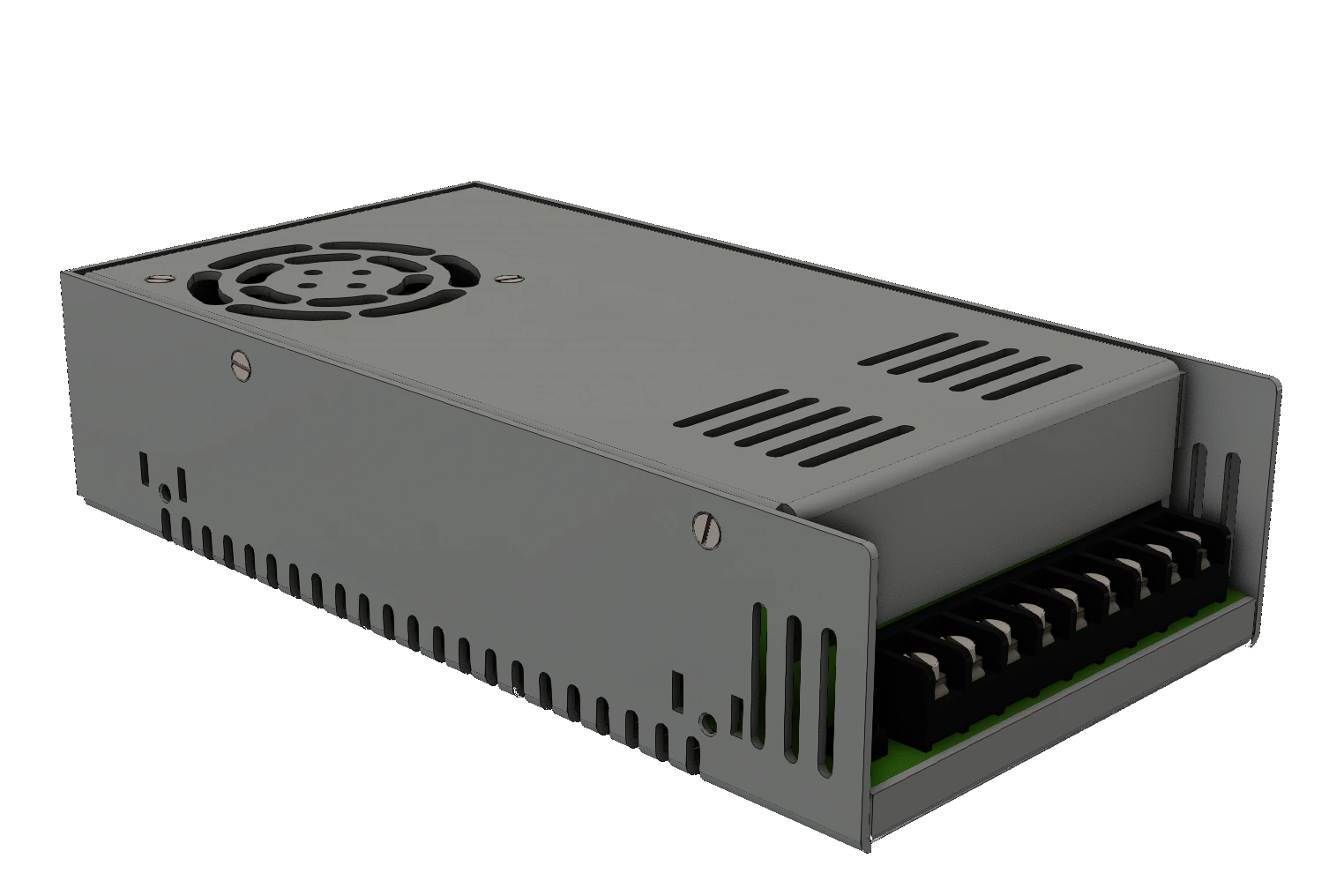
- 300W 12V power supply
- IEC320-C14 AC power inlet
- 120mm Cooling fan
- 14x Ethernet Cables (~12 inches)
- 13x 8/16gb SD cards
For Power Distribution:
- ~18awg stranded-core wire
- 13x JST 2.54mm 2-pin XH male connectors
- 52x JST 2.54mm 2-pin XH male crimps
- 13x Molex 2.54mm 1x2 female connectors
- 52x Molex 2.54mm female crimps
- Protoboard (20mm x 80mm)
Tools
- 3D printer & filament
- Soldering iron
- Wire cutters & strippers
- wire crimpers / needlenose pliers
- Multimeter for testing
- M2, M3, M4 allen wrenches
Like always, all STL and configuration files will be provided on this project’s Github Page so you can print and create your own!
Intro to UDOO
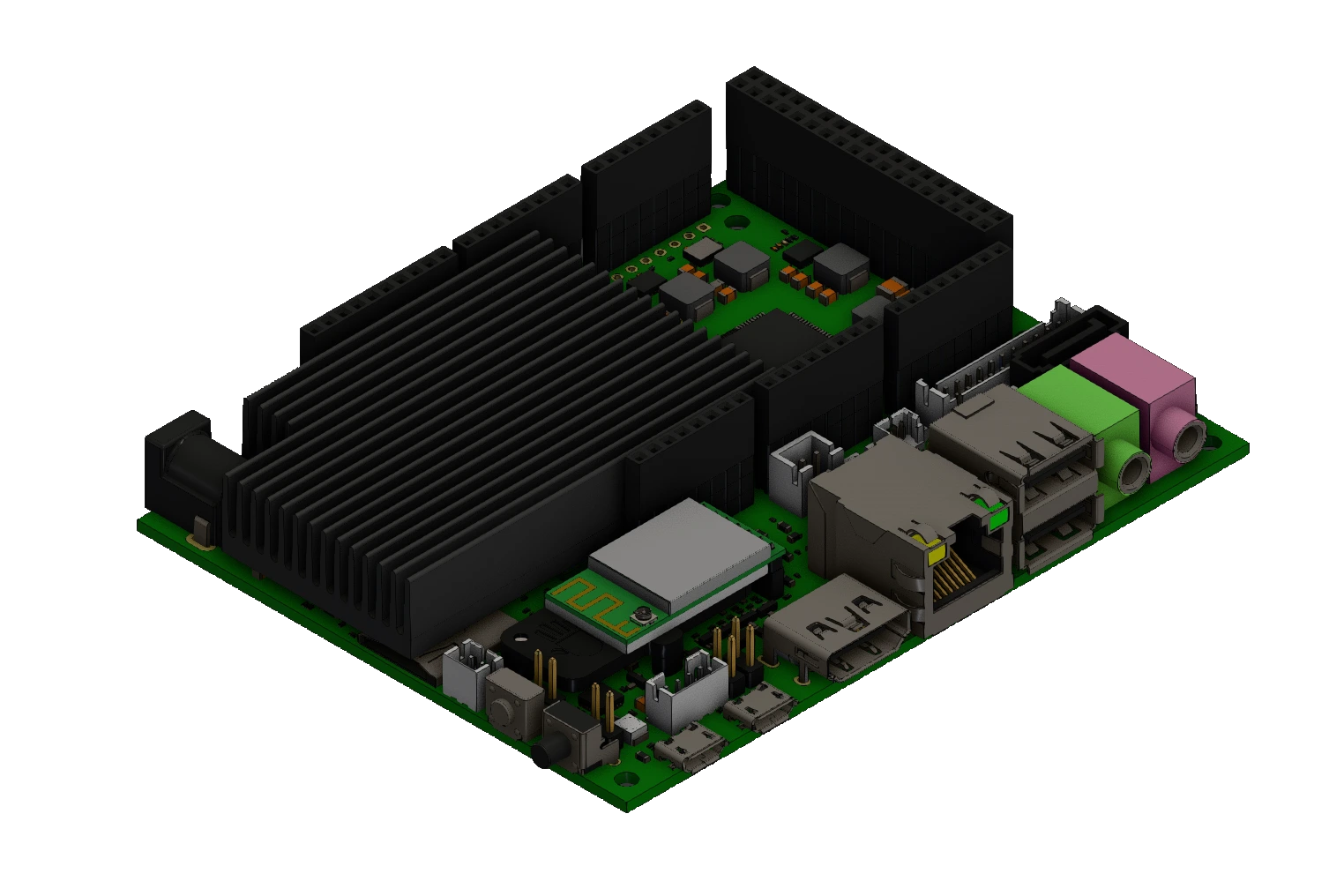
During a ‘spring cleaning’ of sorts at my high school, I was presented with a unique opportunity from the head of house: in the process of getting rid of junk, I could take home one of the Udoo boards that they used in the SMCS program prior to switching to Raspberry Pi hardware. After receiving one board, I was presented with a box of boards that had been thrown away for one reason or another, likely USB or MCU issues. (The Udoo Quad board includes an ATSAM3X8E ARM co-processor to handle GPIO processing for the Udoo Quad’s extensive GPIO headers.) A quick count revealed a total of 17 Udoo boards that had simply been thrown away!
When I saw the amount of individual computers that would have otherwise become e-waste, I decided to take them home and attempt to do at least something with them. The idea popped into my head as soon as I counted them up: I wanted to build a compute cluster.
Out of the total of 18 Udoo boards I now possessed (17 of which were marked as nonfunctional), I was able to get 13 up and running. A few of the boards truly were lost, and didn’t even power on. After that, a few more had USB issues and WiFi problems, but I managed to navigate around those as well.
The Build
This project revolves around loading and writing software for the Udoo Quad SBCs, then assembling them into a structured, functional computing cluster with proper power distribution, networking, and cooling.
Loading the OS
Perhaps the longest part of this project was getting a functional operating system running on just one of the Udoo Quads. Since the company that made the Udoo Quad discontinued it, software support was extremely slim. On top of that, the board was developed in 2013 (with roughly the equivalent processing power of Raspberry Pi 3, or an android phone from 2013), so the most up-to-date OS that they included, called Udoobuntu, was stuck on Ubuntu 14.04 LTS. Additionally, even the versions developed by the community after the Quad was discontinued were stuck at 18.04.
Attempting to boot 18.04 resulted in failure, and 14.04 LTS was too old for the software that I needed to run; dependencies were simply not supported on an OS that old. So, I had to turn to alternative sources for an OS.
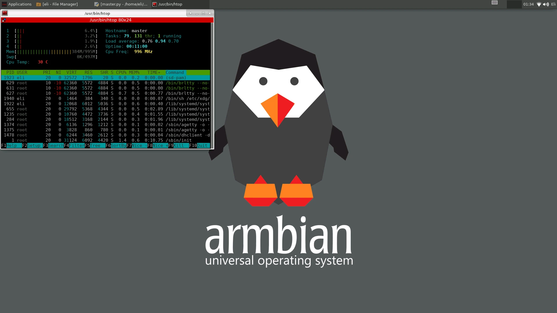
I attempted to modify existing OSes, and did a deep dive on Udoo U-Boot, even going as far as attempting to transplant the U-Boot bootloader onto a more modern OS, but to no avail. Instead, after lots of testing and trial and error, I found a version of Armbian that not only booted on the Udoo board, but also had a desktop environment! (Armbian 21.08.5 Buster, using Linux kernel 5.10.60 and xfce.) This archive was a huge help to me when I found it, and it lists a ton of Udoo-specific Armbian distros. Although some of them failed to boot, the one I listed worked right out of the box.
Software
Now that I finally had an OS that was both modern and functional, I could finally begin setting up the software required to build a cluster. The software that I used to communicate between Udoo boards is called MPICH, which is a lighter weight and portable implementation of the MPI-4.1 standard. MPI stands for ‘Message Passing Interface,’ and is the glue that will tie each of the Udoo boards together. Without it, each board cannot communicate with the others. I also installed MPI4Py, which is a python interpreter for MPICH.
After installing all the required programs on one worker board, the next task was to install it on the remaining 12 boards. This was more tedious than difficult, and mostly consisted of copying the contents of the first board onto another, then updating a few critical files. I used a Micro-SD card adapter plugged into the first functional board, and used the command sudo dd if=/dev/sda of=/dev/sdb bs=32M status=progress to copy the entire filesystem over to the new SD card. This had pretty good success, despite likely not being the smartest way to do it. As a side note, I purchased these SD cards for extremely cheap on Aliexpress. Combined with a sale, I was able to get them for nearly $2.50/unit, compared to a MSRP of about $8/unit from a reputable brand. I bought 18, one for each board, and as it turned out, 5 of them had issues functioning. It ended up working out since 5 boards also didn’t function when tested, but I learned an important lesson involving questionable quality control from non-reputable suppliers.
Another huge help to this project was the tutorials by Tinkernut, and his accompanying blog. His 2-part tutorial on youtube was what I followed to set up my cluster, and I had great success using it. In-depth instructions, and the exact commands he used are available on his blog posts (Part 1, Part 2), and his videos were both entertaining and informative (Part 1, Part 2). Some of the links that he had used were outdated, and I spent quite a lot of time finding the specific versions of software that he used, so all the files can also be found on this project’s github repo.
After repeating this setup for all 13 boards, I finally had the software mostly sorted out. I decided to leave the actual testing program to the end of the project, and instead focused my attention to building a frame for the boards.
Frame
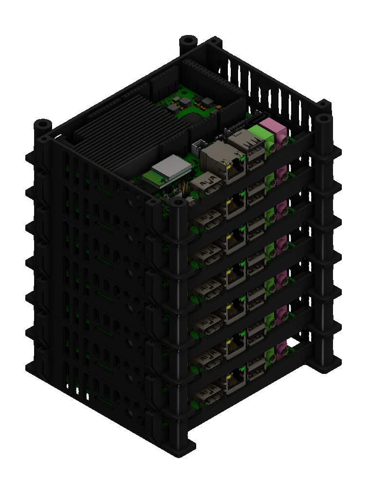
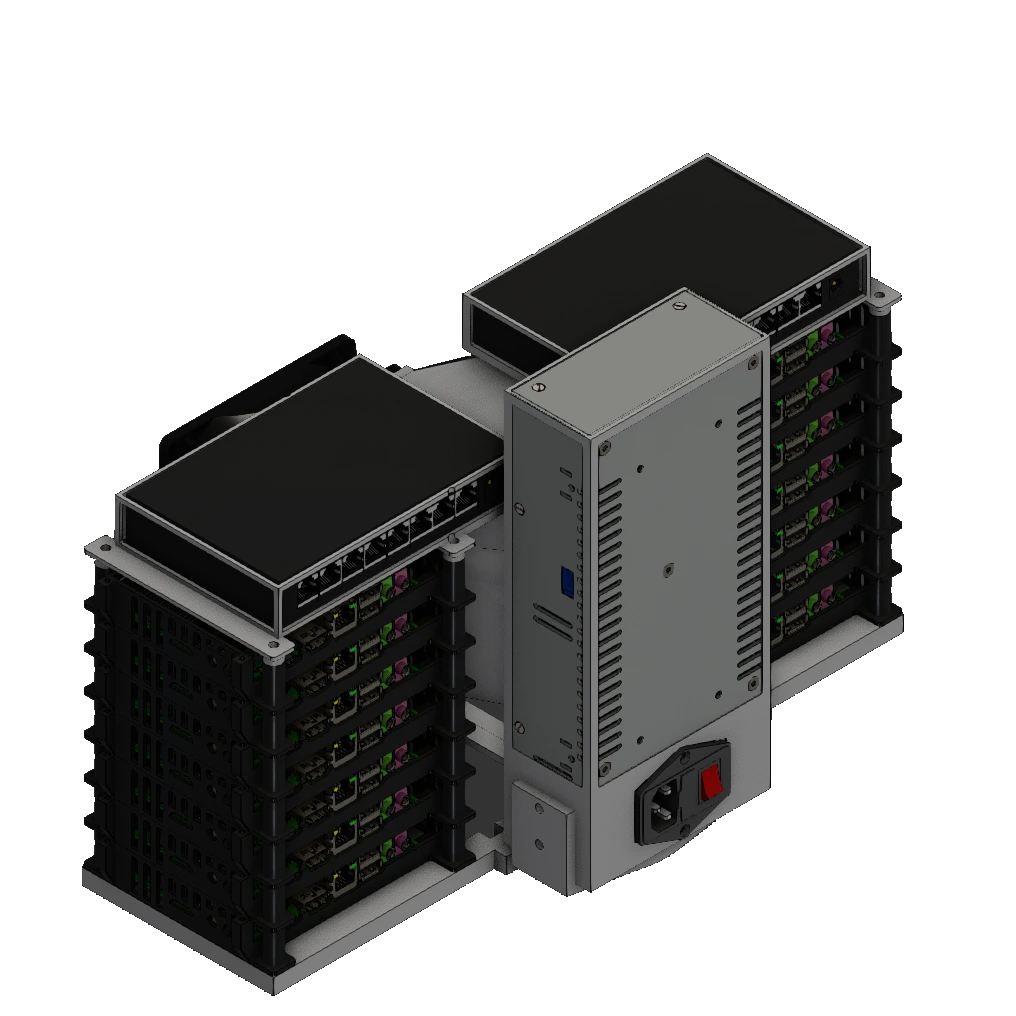
To house all 13 boards securely and provide adequate airflow, I designed a custom 3D-printed frame. The frame was designed with two stacks, each capable of holding up to 7 Udoo Quads stacked on top of one another (although with only 13 boards, one stack only held 6 Udoo Quads). On top of the boards, I designed another mount for the network switch to connect each board together. Additionally, the frame included mounting points for a power supply, a cooling fan, and the power distribution board.
Cooling System
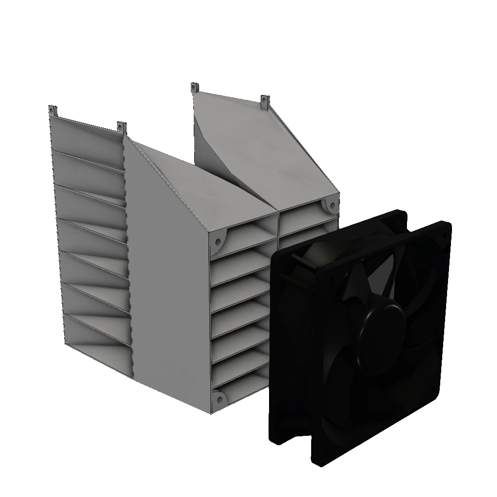
I’m glad I thought ahead to include a cooling system for this project, because the Udoo Quad boards definitely give off some heat. In addition to the heat vents on the case that I found on the internet (I converted it to a .step file, available on github), I designed and 3D printed a cooling manifold that distributed airflow from a 120mm PC fan to all 13 Udoo boards across both stacks. This was absolutely essential to the performance of this project, since otherwise the structure of the boards would have allowed for nearly zero ambient cooling, since they were all on top of each other. All the hot air was exhausted out the sides of the system, which made sure that no warm air was being recycled by the intake fan.
Power Management
The cluster is powered by a 300W 12V power supply I repurposed from an old 3D printer, which ensured sufficient power for all of the boards. Each Udoo Quad received a stable power connection through the built-in JST XH 2.54mm, which was rated for 12v at 2 amps. However, despite each board not taking any more than 6-8 watts under full load during my testing, distributing all that power to 13 boards was another engineering problem I would need to overcome. My solution was pretty hacked-together, but the ends justified the means.
I started by desoldering two of the three high-current screw terminals from an old 3D printer mainboard, the same one I scavenged the power supply from. Next, I retrieved a protoboard and soldered both of them to it. Next, I lined up 40 2.54mm-pitch pins using two 20-pin headers, and used a copious amount of solder to connect the screw terminals to their corresponding row of headers. Looking back, I may have overdone it on the solder, but my largest concern was making sure that each line would be able to carry enough current without heating up.
So, after finishing the soldering, by far the most grueling part of the project was creating each of the power cables. Since I chose to use the JST power port on each Udoo Quad because it meant I could save valuable space by not using the DC barrel jack placed facing the outside of the case, I now had to route power cords to each of the Udoo boards individually. This meant cutting 26 wires to various lengths to fit neatly next to the cooling system manifold. Even worse, I then had to individually strip and crimp 52 terminals by hand; 26 JST XH terminals, and 26 2.54mm Molex terminals. At the time I didn’t have a JST crimping tool, so all of those crimps were completed with a pair of pliers.
After all the wires were measured, cut, and assembled, they were all plugged into their corresponding Udoo Boards. Then, the other end of each wire was connected to the 40-pin header, responsible for distributing the power from the PSU.
Networking
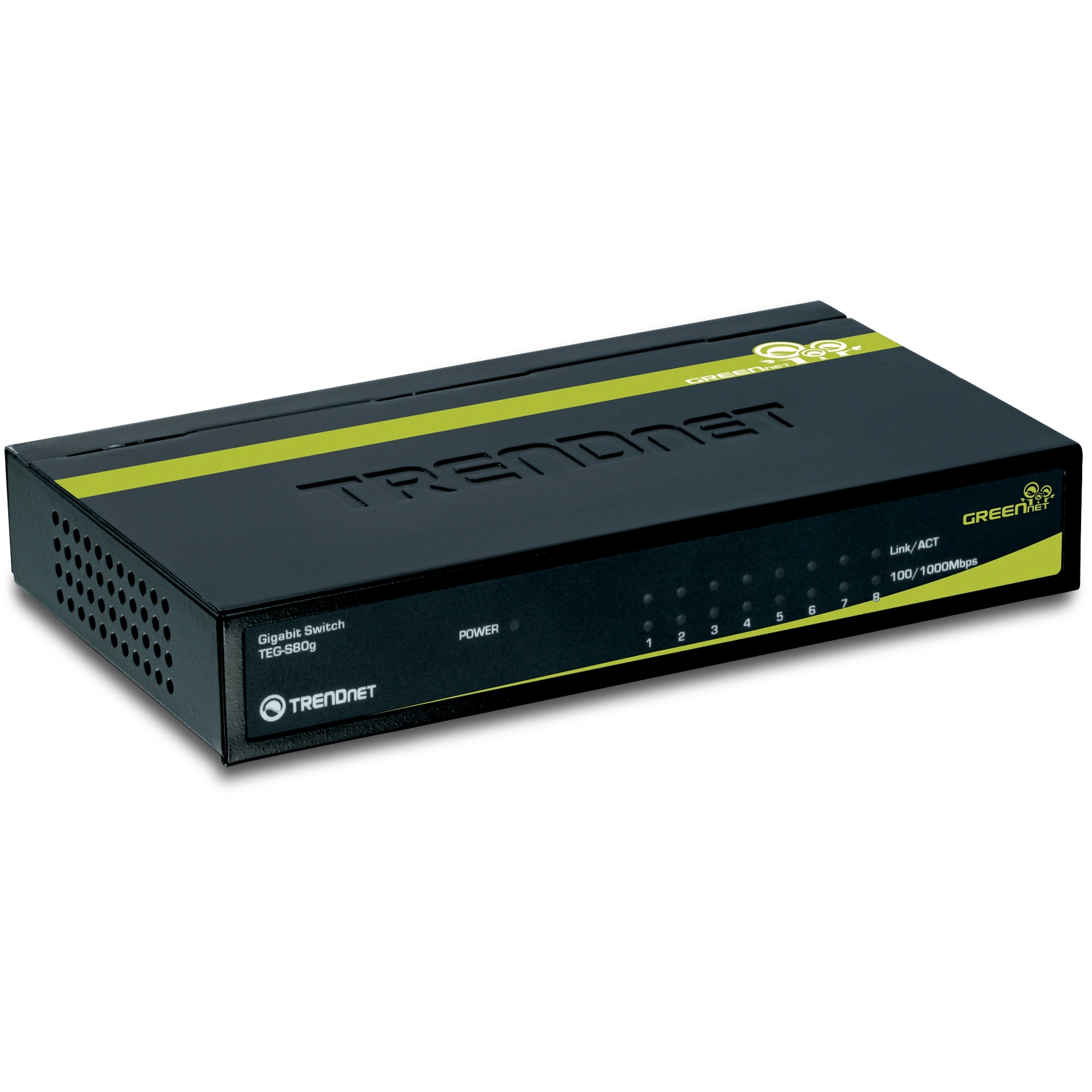
To interconnect all nodes, I used two 8-port network switches (TRENDnet TEG-S80g). Using the 12-inch Ethernet cables that I purchased earlier, I connected each Udoo board to its corresponding switch.
Since my switch had 8 ethernet ports, but I only had 13 Udoo boards, I was not only able to daisy-chain the switches together, but I was left with one extra port for my laptop to connect to, giving me full access to each computer without the need to go through the main Udoo board. I know that isn’t best practice to daisy-chain network switches together, but for my purposes, even with only a 1 Gigabit switch, bandwidth wasn’t going to be an issue.
Now that all the boards were wired up with both Ethernet and power, I could find the IP of each board, and take note of it in a document. Knowing the IP address of each board on the switches’ local network is essential to the next steps in setting up the cluster.
Software, continued
After verifying that each board was powered on and working, I added each of their IPs to a machinefile created in the project directory. Afterwards, running mpiexec -f machinefile -n 13 hostname did not return the name of each board. This is actually good news; I’d be worried if it did work. Instead, I needed to exchange host keys between the controller board and the worker boards in order for a secure data exchange to be facilitated.
The next step after this is establishing SSH keys between each of the worker Udoo boards and the main controller board. I ran the following commands for the controller node:
ssh controller@<controller ip address>
ssh-keygen
cd ~/.ssh
cp id_rsa.pub controller
exit
Then, I repeated with similar commands for each worker node, to connect them to the controller:
ssh worker01@<worker01 ip address>
ssh-keygen
cd ~/.ssh
cp id_rsa.pub worker01
scp controller@<controller ip address>:/home/udooer/.ssh/controller .
cat controller >> authorized_keys
exit
After completing this for each worker node, I went back to the controller node and added the worker’s keys to the controller. Again, I performed this for each worker in the cluster:
scp worker01@<worker01 ip address>:/home/udooer/.ssh/worker01 .
cat worker01 >> authorized_keys
Now, running the same mpiexec -f machinefile -n 13 hostname command returned the name of each board! Now that each computer trusted the controller, it was finally time to test out MPICH’s capabilities. After copying a hello world demo file to each computer, running it worked flawlessly, and each board returned their corresponding ‘hello world’.
Moving onto a more complex program, I copied a md5 hash cracking program to each computer, and ran it. again, it was able to complete the program and return the unhashed value.
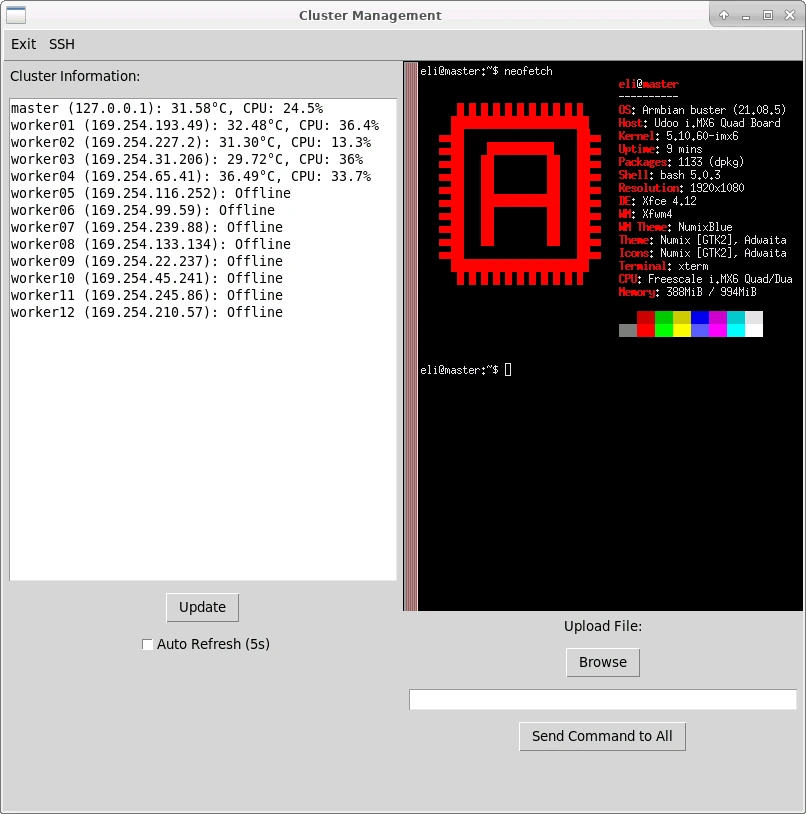
The final thing I wanted to do to complete the software side of the project was to automate the process of running software on each worker simultaneously. So, I created a GUI in python using the tkinter library to handle the following tasks:
- Show the status of each board, including temperature and uptime
- Load a SSH terminal on command for any board I select
- Provide an easy GUI to load a program onto the filesystem of each Udoo Quad with a single click
- Send a command globally to each board, e.g. to remove an old program that is no longer required
Results
After all the work, all the roadblocks I overcame, and all the software I wrote, I timed the program execution of a fibonacci sequence program using all 13 workers. And what performance boost did I receive? 13x? 5x? In fact, it was only a 2x boost in performance compared to a single worker node. I’m not entirely sure why the boost was so small; the test took a fairly long time to run both times, averaging 14 seconds with 1 worker, and about 7 seconds with all 13 workers, which seems like long enough to give all the hardware time to warm up. My code also took advantage of all 13 workers, but perhaps the problem at hand wasn’t really designed for clustered compute and parallelization in the first place. I believe that the program I wrote maybe wasn’t optimized best for my setup, and maybe a better idea would have a longer-term cryptomining test where each board could work on their own separate block, reducing compute overlap that would reduce efficiency. Additionally, issues with network and communication overhead may have played a part, since I was using older routers and wrote all the programs in python, which isn’t the most performant language.
So, what have I used this project for since then? Well, nothing. It’s been a great talking piece, but otherwise it has remained dormant after I tested the performance. This project took quite a while from opportunity to finished product, and in that time I had to push through quite a lack of enthusiasm to get there. Additionally, through my own personal error, I may have permanently damaged a few of the boards.
One day, after testing, I shut down all of the boards using the global command feature on the control panel, and turned off the fan. However, I did not disconnect the power from the boards, and the power supply was still plugged in. I left it unattended for a few hours, and when I came back to continue work on it, the entire frame was hot to the touch, and was radiating heat from all sides. I quickly turned the fan back on to 100% airflow, and the air that blew out of the vents was the hottest I had ever felt from this project. Turning the boards back on, two of them refused to post, and would not display a HDMI signal, respond to the control panel’s requests for a SSH session, or even respond to a global command. Apparently, if power is still supplied to the Udoo Quad through the JST power connector, enough current will still flow through the computer to damage it. I was surprised there was no overheating protection on these boards, but that may have been because all the control logic was powered off, making this hardware bug even more vicious. This was the final nail in the coffin for this project, and I lost what little motivation I had left to polish this idea up, so technically this project was never fully finished. Some of the issues powering the peripherals for the cluster are still present today, and I talk about them in depth in Potential Improvements
Lessons Learned & Future Improvements
What Worked Well
-
The cooling system worked really well, and the manifold worked exactly as intended. Designing the manifold used a lot of more advanced CAD techniques that I had to learn for the purposes of this project, and they definitely paid off. With the cooling fan running, the temps didn’t rise above ~40 degrees, so I consider it a success.
-
The 3D-printed frame did everything I designed it to do. This was one of my first projects where I assembled every model in CAD, which pointed out a lot of the flaws with my design that I could fix before printing the actual parts. Although the frame is a bit flimsy (if I could rebuild it, I would just spend the extra filament to strengthen the base of the frame), it’s very stable when set down on a table or desk. Surprisingly, the tower isn’t top heavy at all, despite how it looks.
-
I was surprised by how straightforward the networking was. All I had to do was note down the IP address of each of the boards, and MPICH handled the rest. I definitely went into this project fearing the networking aspect of it, but I’ve learned a lot from this project, and I now feel much more comfortable with networking-related programs and projects.
Potential Improvements
-
The mount for the PSU is definitely flimsy, however. The walls were thin, with the intention to make it as easy as possible to squeeze the power supply into place. However, this backfired when it came to actually plugging the device in after screwing in the power socket. Because the walls holding the PSU and socket in place were so flimsy, pressing the plug into it made it bend quite a bit, and I don’t have too much confidence in its long-term strength. However, it works for now, so it doesn’t affect the functionality of the project yet.
-
I considered leveraging more advanced software like kubernetes using this cluster, but I had technical difficulties setting it up across multiple computers due to dependency errors with Armbian, and I wasn’t particularly interested in doing more bugfixing and troubleshooting after all the work I had done to make MPICH and Armbian work in the first place. This could definitely be a cool route to continue on in the future, after my exhaustion from troubleshooting hardware and software issue with this project wears off.
-
As an addon, I created a smaller control box that held circuitry to modulate the speed of the fan, as well as the power running to the network switches. However, there were some serious issues with my approach. Modulating the speed of the fan was handled simply by using a buck converter receiving the 12v input from the PSU, which isn’t really best practice, especially since the fan came with extra pins specifically for a PWM input to modulate speed in software. I didn’t want to include a separate microcontroller though, so I stuck to the voltage-modulated method. As for powering the network switches, I made a much more fatal error.
I designed the container for the control circuitry before I had fully thought out the design of the circuitry itself. So, in addition to the buck converter to control the fan, I used two 5v linear regulators to provide the output for the two switches. Since each switch was rated to draw up to 1 amp, and these 5v linear regulators were fed from the 12v power supply, each linear regulator had to dissipate 7 watts of heat. (For reference, the TO-220 form factor that the linear regulator was packaged in has a maximum heat dissipation in open air of 2 watts.) Beyond that, the network switches constantly switched on and off, likely from the lack of inrush current protection. (I didn’t include any capacitors on the output either.) Between these two issues, the linear regulators overheated after only a few minutes of use, and the switches never got enough power to start up and function. As such, the switches needed to be powered separately using their included power bricks, bringing the total amount of outlets required from one to three.
Knowing what I know now, I could have immediately deduced that using linear regulators to power a significant load, especially at a 7 volt drop is a terrible idea. Using another buck converter tuned to 5v with extra decoupling capacitors on the outputs would have resolved the issue, and kept the control box significantly cooler, as well as reduced the number of plugs required back down to the ideal amount: just one.
Conclusion
This project was an exciting foray into distributed computing and system clustering. It not only let me learn a plethora of new software and hardware skills, but it also saved nearly $1800 (at MSRP) of e-waste. If you’re interested in building your own, check out the full source code and 3D print files on GitHub. Thanks for reading!