Recently, I've been very interested in creating circuit boards for my various projects. However, in the past, my boards haven't been much more than basic breakout boards; they simply rerouted existing traces away from the GPIO of the SOC or microprocessor I was using, and placed them in accordance with the footprint of whatever sensor breakout board I chose. In fact, I had never truly completed a PCB project using anything more than off-the-shelf sensor modules. This project has been my first deep-dive into actual circuit board design and production, and I've learned so much along the way.
Materials
The materials and tools list for this project is a bit different from usual, since this post will only be covering the PCB design. The full BOM can be found here. The actual blimp, as a part of the Falcon Flight project, will be discussed in another blog post.
Like always, all .GERBER and related schematics will be provided on this project's Github Page so you can order your own!
The Build
This project revolves around designing a fully functional motor hat for the Raspberry Pi Zero 2W, which is the brain of this blimp. I learned so much over the course of this project, that my criteria and constraints changed multiple times. Here's what I settled on:
Constraints
- The circuit board must be no larger than the footprint of the Raspberry Pi (65x30mm)
- The circuit board must be lightweight, and must have all components assembled on a single side
- The circuit board must be made from common, reputable, and documented components
Criteria
The PCB must have the following functionality:
- USB-C charging
- A Boost converter to supply 5V to the Raspberry Pi
- Separate batteries for the Raspberry Pi and motors drivers
- Motor driver circuitry to drive up to 4 motors
- An accelerometer/gyroscope/magnetometer
- At least some extensibility for the future
My criteria and constraints changed quite a bit with each revision, and there were more of those than I'd care to admit. I'll go over each version, the new features on each, what went wrong with them, and what I learned.
Top view of the Falcon Flight embedded controller board, revision 1.0
Revision 1.0
This board was my very first attempt at designing a simplified PCB for the Falcon Flight project, and I made it over a year ago from the time this blog post will be released. It featured two sockets for up to 4 motor drivers, 4 motor I/O pins, a plug for a MPU6050 breakout board, two battery connectors, and a Raspberry Pi header. Like some of my earlier custom PCBs, this board was just a breakout board that routed traces from the Raspberry Pi's GPIO header to pins on ICs soldered to the board. However, I still learned some skills with this board:
What was different?
This circuit board taught me two new things:
- The value of thicker traces for higher current applications. In retrospect, 1mm-thick traces were a bit overkill for motor drivers with a maximum current rating of 1A, but they certainly didn't heat up under load.
- The value of GND pours. In this early stage of the project, I still didn't understand the additional values of GND pours, such as reduced impedance and noise isolation. At the time, I only understood that it made routing GND very easy and painless, and that it would help with heat dissipation. In fact, the datasheet for the driver was what clued me in to this design choice.
What worked?
This circuit board was flawless! Its simplicity made it a likely candidate for success, and I had no issues with the motor driver traces or the SCL/SDA lines to the MPU6050 accelerometer/gyroscope. The battery connectors also worked well, although the polarity was incidentally reversed. Thankfully, just flipping the plastic connector 180 degrees fixed the issue. I designed the board with the battery connectors at the back of the PCB, but facing forwards, so that the batteries would take up space along the length of the Raspberry Pi, rather than sticking out the back, which could affect weight distribution when put on a blimp.
What didn't work?
For starters, the Raspberry Pi Zero 2W was dead slow. I was powering it directly with a 4.25v/300mAh FPV drone battery, so it was certainly not receiving the 5 volts it needed to run at full speed, and it showed. The Pi took longer to boot up, ran applications slower, and had general instability, especially as the battery got lower and the voltage dropped proportionally, since there was absolutely zero battery management.
Additionally, some of the motor drivers did not work. The motor driver that was provided to me and the rest of the students working on the Falcon Flight project during my 10th grade year was the SN754410 motor driver chip from Texas Instruments (datasheet). Now, this was a fantastic chip when it was released... in 1986. Since then, it has become significantly more dated. Besides the large amount of heat produced under very light loads (driving up to two 716 coreless DC motors), the largest issue with this driver was it's minimum VIN was 4.5v, far below the 4.25v maximum rating for the FPV LiPo batteries we were using. Some motor drivers were still able to drive at the ~3.7v that the batteries would produce, but that was more of an effect of the silicon lottery than the intended use case for this IC. As such, I had to go through a handful of these chips before I got two that worked.
What did I learn?
The main takeaway from this revision was that although a custom PCB reduces weight, between the heavy motor drivers and the second breakout board for the sensor, a large amount of that weight reduction was diminished. At this point, I decided it was time to revisit SMD assembly if I wanted to get the weight down as low as possible.
Top view of the Falcon Flight embedded controller board, revision 2.0
Revision 2.0
This next board was my first delve into SMD componentry since my first-ever custom PCB, and it had some much-needed improvement over Rev. 1.0.
What was different?
Besides being entirely composed of SMD components, this board had new features, like:
- A 3.7v -> 5v boost converter (using the MT3608 IC)
- An integrated USB-C battery charger (using the TP4056, an IC I already had prior experience with)
- 2x Quad-half bridges, for a total of 4 motors with bidirectional control (using the DRV8833RTYR)
- A MPU6050, soldered directly to the PCB
What worked?
The boost converter, charger, and sensor all worked flawlessly. the charger was configured for up to 200mA charging, which was sufficient for the FPV LiPo battery, and charged consistently without too much excess heat. The boost converter worked like a charm, which surprised me because it was the only component block that I did not have prior experience with. It generated a fairly stable 5v signal, enough that the Raspberry Pi and motor drivers were able to run off of it without much trouble. Finally, the MPU6050 worked perfectly, and provided me with very accurate data for acceleration and rotational velocity.
What didn't work?
A recurring theme throughout this blog post will be me needing to read the datasheet more carefully. When wiring up the motor drivers, I placed each pair of motor output pins (2 pins per motor) on the IC pads labeled AOUTx and BOUTx, while the datasheet dictated that each motor pair should be connected to xOUT1 and xOUT2. This meant that the leads of the motors were electrically isolated from one another, and as such no current could flow.
What did I learn?
The inner working of an H-bridge on a silicon level became much more clear to me as I diagnosed the issue with my motors not being driven properly. Although I found what was wrong with my circuit just by investigated the datasheet's diagram more closely, I now have a much better grasp of how a h-bridge works.
Top view of the Falcon Flight embedded controller board, revision 3.0
Revision 3.0
This revision was much more advanced than revision 2.0. However, after actually ordering this board and testing more thoroughly, a few more critical problems were revealed to me.
What was different?
To start, this design had much more robust passives for the driver ICs. I added 10kΩ pulldown resistors on the IN and nSleep lines for the motor drivers, as well as beefed up the input capacitors with an additional 47µF bypass capacitor tied between 5v and GND.
The larger change for this revision, however, was the sensor suite. Despite the huge amount the support for the MPU6050 IC, it was a 15 year old chip at this point, not to mention that it reached its EOL in Q4 2024. I had an important decision to make: stick with the EOL chip because of its widespread software and forum support, or transition to a new IC with a longer lifespan ahead of it. I chose the latter, and settled on a new 9-DoF sensor suite. I chose the BMI270 6-axis accelerometer and gyroscope, and the BMM350 3-axis magnetometer, both from Bosch Sensortec.
What worked?
The 9-DoF sensor suite worked flawlessly on the first try! This really shocked me, especially after running into the earlier issue with the poorly-wired motor drivers. This still seems like the most complex group of components, even on the final revision of the board, so I was stunned to find that both sensors were detected when I ran i2cdetect -y 1 on the Raspberry Pi Zero 2W, although it would take a bit more work to get actual data out of them.
I was able to recess the 8-pin motor header further into the board, which shrunk the total footprint of the model even further.
What didn't work?
This is the revision where I nearly panicked. At a first glance, I thought that this was the revision. The sensor suite worked consistently, and all of the motor drivers worked too. I also had consolidated the number of batteries required for my board, decreasing the total weight! This was the critical flaw in my board design, however.
Motors are considered inductive loads. This means that they have the properties of an inductor, but with a small caveat. When changing state abruptly, such as from standing still to full throttle, they consume a large burst of energy for a short period of time. This occurs because a motor at standstill does not exhibit a significant inductive effect; it instead allows current to run through the motor windings uninterrupted, save for the resistance of the winding itself. This is called inrush current, and although this entire phenomena occurs on the order of 10-6 seconds, it is enough to divert enough electricity away from the Raspberry Pi to cause a brownout state. So, when I turned on one motor at a time, I saw no issue; the bypass capacitors in the circuit were enough to continue powering the Raspberry Pi through a single motor's startup. However, when I tested more than just a single motor turning on at a time, the entire system shut down.
This was bad. Thankfully, I discovered this problem before placing an order for a few dozen of these boards, which would've been a larger headache, but this still meant I would need a large overhaul on the entire power distribution system.
What did I learn?
This was the first time that I truly understood what pulldown resistors did, and how they affected the circuits I added them to. Previously, I just wired them up and trusted that whoever made the reference schematic knew what they were doing. Even better, after taking AP Physics this past year, I now knew the math behind how they worked, allowing me to understand them on a basic, conceptual level.
More importantly, however, I learned that motors can pull a lot of current when spinning up! And worse yet, that current spike isn't visible on a multimeter. I'll certainly never make a mistake like this again when designing motor driver circuitry.
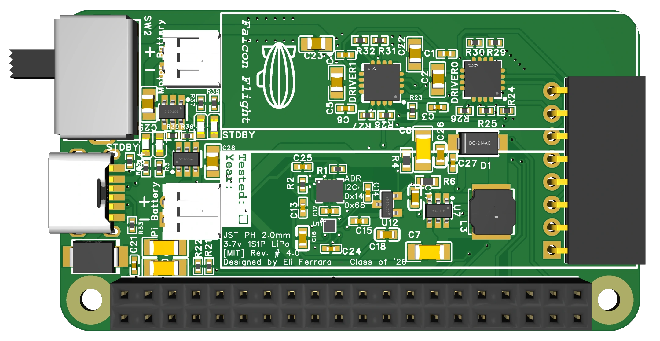
Top view of the Falcon Flight embedded controller board, revision 4.0
Revision 4.0
Revision 4 was a bit of a rushed design, and it never actually made it past the design phase. As such, the format for this section will be a little different.
At this point, I was beginning to feel rushed to get the design finalized so that I would have time to have the boards manufactured and assembled, and so I let some of the design constraints loosen to ease my development. I knew that I would need to add a second battery to the design; one to power the Raspberry Pi, and one to power the motor drivers. The alternative option to fix the inrush current issue would be to slap on a large, bulk capacitor on the input of each motor driver, but the amount of capacitance required to successfully and consistently smooth the ramp-up current of 4 DC motors at the same time mandated the use of one or more electrolytic capacitors. These are fantastic, but also comparatively heavy and tall. Long story short, they wouldn't fit on the board. So, I needed two electrically isolated batteries, with a switch connecting them to their respective circuits. On top of all of this, when more closely inspecting the datasheet for the switch I had chosen in revision #3, I found that it was rated for 500mA at most. Since the Raspberry Pi and motors could easily pull more current than that under full load, I felt that I needed to switch to a beefier switch, not only capable of switching two isolated power rails at the same time, but also capable of handling ~1A of continuous current.
This idea wasn't ideal, although I did try it with revision 4.0. The PCB had a much larger footprint than before, measuring 65mm x 36mm, although the 8-pin motor header was fully recessed into the PCB. While designing this board, however, I came across another issue that I couldn't afford to ignore: it really isn't best practice to pass all of the battery's current through your switch. As I was combing through LCSC for DPDT switches with a 1A current rating, I barely saw any results. This is mainly because switches likes these aren't intended to pass all that current continuously-- they're made to pass a small amount of current into the gate of a FET, for the transistor to do the heavy lifting. By creating the switching circuitry in this way, I could avoid the increased wear and tear on the switch caused by switching such high current, which could cause pitting on the internal contacts of the switch and reduce the number of lifetime cycles.
Having two electrically isolated batteries raised another challenge: charging. The previous charger that I used was a TP4056, which is an ancient but very popular and well documented linear regulator-based Lipo battery charger. That IC also required two other chips to make it work, the DW01a and FS8205a ICs. In addition, the TP4056 only comes in a SOIC-8 package, which was too large to fit two of them on a single board. So, I switched to a much more modern charging IC, the TP4057. This IC is packaged in the SOT23-6 form factor, so it is significantly smaller than the TP4056. Additionally, it doesn't require any of the extra supporting components for battery protection that the TP4056 does, since those features are built in. By switching to this battery charging IC, I was able to squeeze two of them onto the board alongside the second battery connector, while still maintaining enough space for the battery FETs.
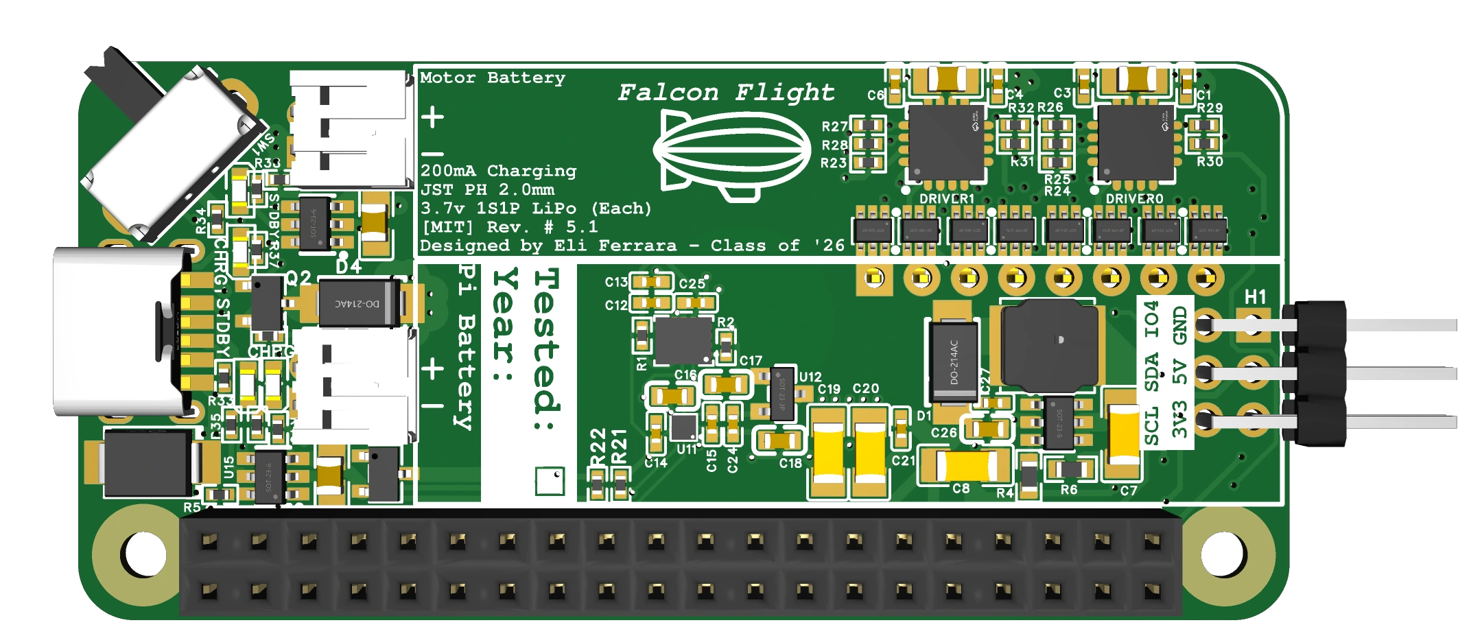
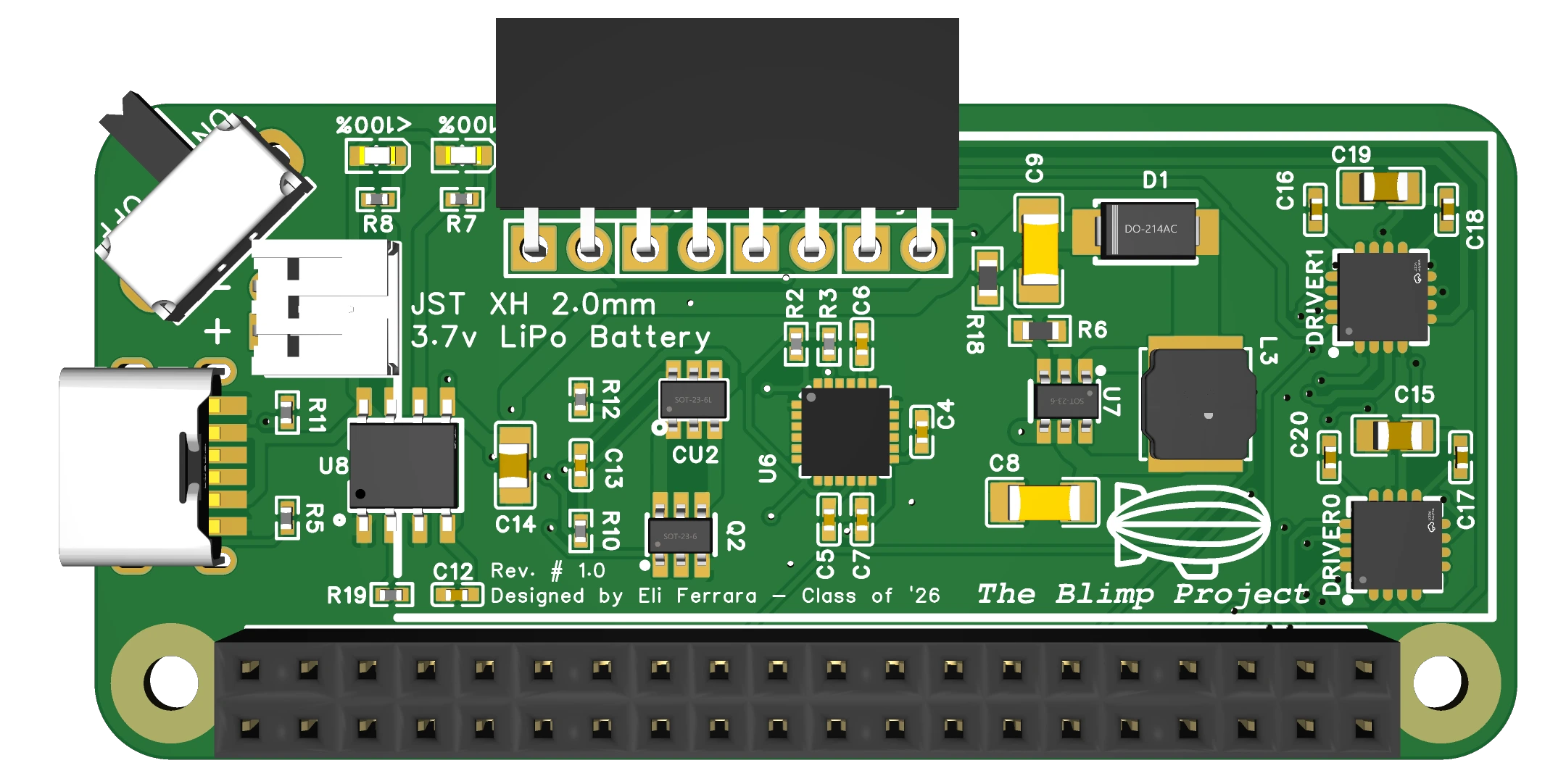
Top view of the Falcon Flight embedded controller board, revision 5.0
Revision 5.0
Revision 5.0 had some much needed corrections, but also exposed a handful of other errors. The PCB was back to its original 65x30mm footprint, but there were still issues with the boost converter, the new power handling circuitry, and the motor drivers themselves.
What was different?
This circuit board had a few major changes from the previous version. Firstly, I got rid of the large, ugly DPDT switch that was hogging all of the space on the top left of the PCB, and replaced it with a much sleeker SPDT switch. Technically it could have been a SPST, but I chose to just not use the other pin on the SPDT. Next, I implemented the FET-based switching circuitry to power the Raspberry Pi and the VM pins on the motor drivers. I used the DMP2035U-7 P-channel MOSFET, which meant that by default, the gate would be closed. However, using a small 100kΩ resistor connected from the positive terminal of the battery to the gate of the MOSFET, the circuit would be opened by default as long as a battery was plugged in.
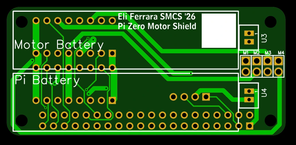
I also had a realization: I could place the 8-pin motor header on the underside of the PCB, freeing up that area for more componentry. I had wanted to avoid this, because I wanted all my components to be assembled on one side of the PCB, but after seeing that adding two batteries to the PCB would take up a much larger footprint, I decided that my only option would be to shift a few of the easier-to-solder components to the underside of the board and solder them manually. I tried to avoid this because having JLCPCB assembly components on both sides of the PCB is much more expensive than just one, and I wanted to avoid manual soldering as much as possible. However, manually soldering 8 pins per board after the fact was a price I was willing to pay in order to get back down to the 65x30mm footprint of the Raspberry Pi Zero 2W.
What worked?
The FET circuitry succeeded in turning on the Raspberry Pi and motor drivers, but it had trouble turning them off. I'll explain that more in the next section. Besides that, the circuitry for the single switch to toggle both batteries simultaneously worked as designed, which was a big win, freeing up more precious space for the FETs. Without the smaller switch, all components likely wouldn't be able to be placed on the board. Finally, by moving the 8-pin motor header to the bottom of the PCB, I freed up enough space to add a GPIO breakout! Initially I had thought that if students wanted to add other sensors they would have to solder wires manually to the back of the 40 pin GPIO header on the Raspberry Pi. This wouldn't have been a huge compromise, since I already included the most popular sensors on the board to begin with, but it still didn't quite feel like it matches the spirit of SMCS, so I'm glad I managed to find room, if only for 6 pins. (GND, 5V, 3V3, SDA, SCL, and GPIO4)
What didn't work?
Unfortunately, a handful of other errors had accumulated during this redesign. There were three in particular that were especially apparent:
-
During my revisions, I had changed the diode in the output loop from a SS34 to a SS54. At a first glance, this seems like a generally good move to increase the current capacity of the output loop. The SS54 diode is rated for up to 5 amperes, while the SS34 is rated for only up to three. However, the datasheet tells a different story. Although the SS54 is rated for up to 5 amperes, its major drawback is the increased junction capacitance. By switching diodes, I increased the capacitance of the output loop from around 250pF, which is not ideal but compensable, to 500pF, which was just enough to create instability. After running for around 30 minutes, the boost converter would temporarily fail, letting the Raspberry Pi fall into a brownout state, requiring a reboot.
-
I mistakenly added a diode bridging the drain of the power MOSFET to its gate, which would have left the MOSFET permanently powered on after its first activation. This was a pretty silly design choice, birthed because I thought that potential flyback from the motor drivers would cause damage to the FETs. Looking back on it now, that design choice wouldn't have even assisted the FETs from flyback voltage if it managed to make its way through the motor drivers, which brings me to the third and final error I made.
-
The DRV8833 IC from Texas Instruments advertises a form of flyback protection, but I have found that to be barely functioning at best. The weak clamping diodes found in the IC didn't hold up to extended abuse when I pushed the driver to its limits, and after slamming the motors from forwards to reverse to forwards again a couple times, they gave up. Now, this typically wouldn't be a problem for almost any other use case-- anyone with the slightest understanding of what they were designing would understand that DC motors are inductive loads, and that they need a few milliseconds to de-energize before reversing direction entirely. I was not designing this board for professionals, however; I was designing it for students, and I know firsthand that I personally slammed the motors in reverse directions more times than I care to admit when I used the old motor drivers for this project in 10th grade, before I knew better. Even in this case, a simple, short delay added to the code would prevent this issue from ever manifesting. I didn't want to count on this, though, so I had to find a solution.
The solution is simple enough: just add better clamping diodes to absorb any inductive kickback and clamp it to VM or GND. So I tried to implement that, but the board was already so space-constrained that I couldn't make the wiring fit. You can see my layout attempt in the image above.
What did I learn?
My experience with the poor diode choice for the output loop on the boost converter really opened my eyes to something I had never fully considered before. I mean, the issue was the junction capacitance? 500 picofarads is such an astronomically small amount of capacitance, and yet it was enough to cause a failure in the boost converter, rendering the majority of the board unstable. I never fully understood all of the small details in some of the datasheets that I read, and how important those specs could be in certain applications until this experience. Going forward, this is an especially valuable lesson for me to keep in mind.
And finally, again, motors are an inductive load! That means that they not only consume a large amount of current on startup, but that they discharge a large amount current when slowing down. In fact, any change in voltage is going to induce some change in current in the motor, just like it would in an inductor. Good to know. I'm sure I won't be making this mistake anymore.
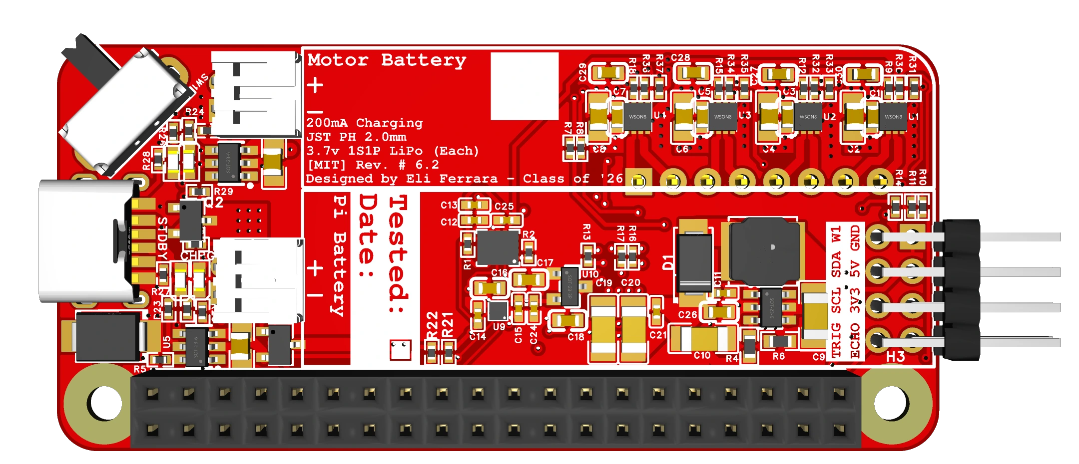
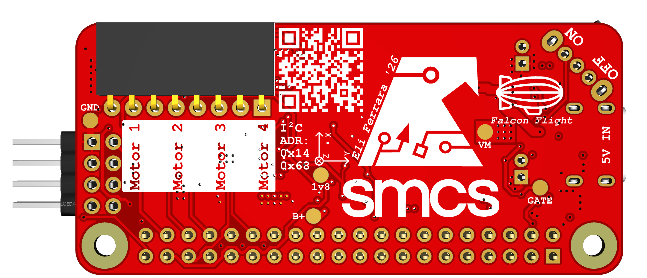
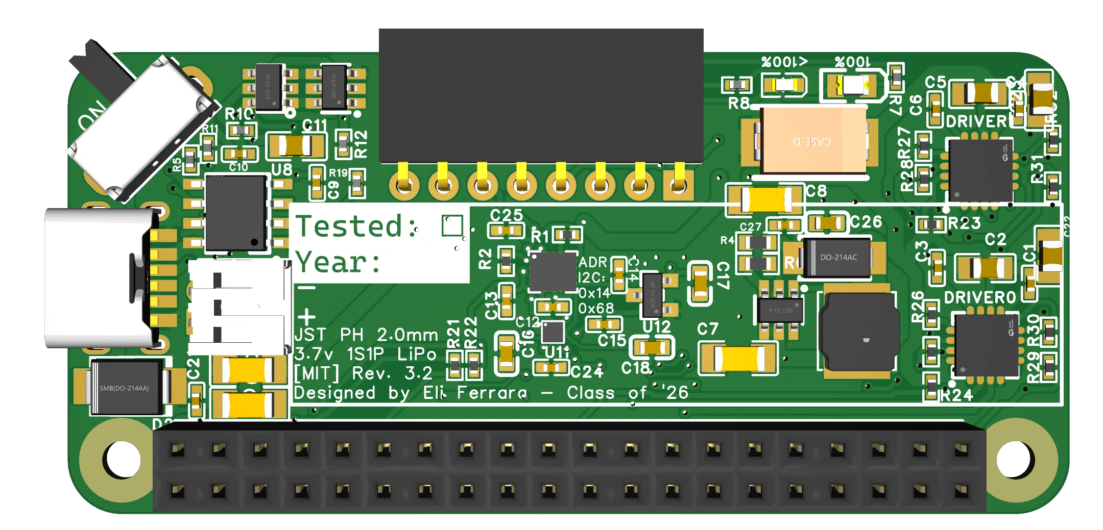
Top view of the Falcon Flight embedded controller board, revision 6.0
Revision 6.0
At long last, we've reached the final revision. This revision is the one that is currently in production, and will be used by dozens of students for the Falcon Flight project in the PHS SMCS program.
What was different?
Quite a bit, although many changes were pretty small. Starting with the largest change, I completely changed the IC I was using to drive the motors. Previously, I used two DRV8833 ICs, which were each quad half-bridge motor drivers chip in a WQFN package. I switched to using four DRV8212p ICs, which are dual half-bridge motor driver chips, but instead of being in a 4x4mm WQFN package, they were in a 2x2mm WSON package. This was genuinely a fantastic choice of driver chip for a few reasons, and a great example of why it is important to pick the right IC for the job:
- This motor IC has built-in motor slamming protection circuitry. Inside the chip, there is a small controller that will stage the dead-time generation for sudden reversals, making the IC immune to flyback events that could be brought on by such occurrences. This controller also means native PWM processing, so motors can now have more than three states.
- Despite needing 4 ICs now instead of 2, the ICs themselves are 4 times smaller than the old DRV8833s, so fitting them in was a breeze, with the added bonus of the output pins being very close to the actual motor terminals themselves. Additionally, one motor driver failure only affects one motor, not two like it would with the old DRV8833 drivers.
- Even moving to a smaller footprint, I was able to provide a generous ground plane around each of the motor drivers, and as such feel confident that the drivers will be able to perform at their peak 4A current rating, without being hindered by temperature throttling.
- Speaking of temperature throttling, this IC has a wide variety of protection features built into the onboard controller, including supply undervoltage lockout (UVLO) that prevents the IC from being supplied with too low a voltage, output overcurrent protection (OCP) which prevents the IC from supplying more current than it can handle, and device overtemperature detection (TSD), which prevents the IC from runaway thermal damage.
- Among the nice-to-have features that this new chip brings are the lower minimum voltage rating, at just 1.65 volts, and the much more modern manufacturing date, so this chip will have support for years to come.
Besides the motor driver change, which was certainly the largest, I also implemented some smaller changes on this final revision:
- I reverted the diode in the boost converter output loop from a SS54 to a SS34 diode. While I could have potentially found a better diode with even less junction capacitance, most commercial boost converters using the MT3608 also use the SS34, so I figured I was safe. Additionally, I didn't want to mess anything up at this point and require another testing round of boards.
- I increased the GPIO pin header breakout from 6 pins to 8 pins, now adding two more programmable GPIO breakouts. I chose GPIO pins 23 and 24, and dedicated them as the
TRIGandECHOpins, to be used for an ultrasonic distance sensor. I took special care to make sure these pins were generally noise isolated, since most ultrasonic sensors require timing calculations to be performed on the Raspberry Pi itself, rather than on-sensor. - I removed the series diode I had placed between the drain of the motor driver FET and the motor drivers themselves. I had initially placed it there in the hopes that it would serve as a last line of defense against flyback events from the motors, but after realizing that the new motor drivers had built-in flyback protection, I traded that unnecessary diode for the extra ~0.55 volts I would gain by removing the diode's voltage drop.
- I added series resistors on all of the GPIO pins leading into the motor drivers. This was a bit overkill, but I could see a scenario where the GPIO pins could be damaged if the board wasn't powered on properly. So, 10kΩ resistors were added in series with each of the input pins on the motor drivers in order to protect them from overcurrent events, while still allowing plenty of headroom for data signals to be transmitted.
What worked?
Everything! The sensor suite, battery charging, boost converter, motor drivers, and GPIO breakout all work. I couldn't be more happy that everything succeeded, especially with the amount of work and revisions I put into this project.
What didn't work?
Nothing that I know of yet! I can only hope that I designed my board well enough to withstand the next few years of abuse as the rising SMCS sophomores figure out how to use it to bring their projects to the next level.
What did I learn?
The importance of choosing the right IC for the job. The DRV8212p was a lifesaver of a chip, and without it, I'm not entirely sure I would have been able to complete the project.
Manufacturing
Now that I had settled on a final design, I had to go through the process of getting the board manufactured. For all of the previous physical revisions, I just ordered them in green silkscreen and HASL plating, since that was the default option from JLCPCB, and the cheapest. However, since I would be ordering 25 boards that would be used for many years, and would be handled often enough, I elected to use a red silkscreen to match the SMCS house colors, as well as gold ENIG plating on the pads, to improve board longevity and reduce any danger associated with lead HASL plating.
In addition to PCB manufacturing, these boards would also be assembled by JLCPCB. Throughout the whole process, I was cognizant of the BOM, so that I wouldn't have too many components on the board if I could help it. This was important, because each extra part incurs a $3.00 fee to load onto the pick-and-place machines in their warehouse.
The pricing wasn't that simple, however. When I was just using the MPU6050 as my sensor suite, the board could be assembled using JLCPCB's 'Economic' process, which was eligible for all components with a footprint equal to or larger than 0402. However, when I switched to the improved sensor suite with the BMI270 and BMP350, both of those sensors carried footprints that JLCPCB interpreted as smaller than 0402. Because of that, the board was only eligible for 'Standard' assembly, which meant a $3.00 fee per component, regardless of component class. This was different from economic assembly, which would waive the loading fee for preferred components, like SMD resistors/capacitors of common values.
Regardless, after optimizing the board's BOM, I got a quote for ~$700 for 25pcs, and I ordered them. About two weeks later, All 25 boards arrived.
Testing
In order to ensure that every board I turn over to the SMCS program is functional, I decided to individually test every feature on every board. This meant testing the sensor suite, the battery charging, the power supply circuitry, and the motors. Testing the first three was easy, since there were clear indicators of proper functionality. However, testing the motors was a little more tricky. While not impossible, it would have been tedious to plug in all 4 motors for each board, then test them one by one, listening to the sound of the motors to determine if they were moving clockwise or counterclockwise. In addition, while my motors work, a common issue with this project was that not all of the school's motors worked, for one reason or another.

Top view of the Falcon Flight motor testing board, featuring eight red LEDs, each in series with a diode and resistor.
So, to eliminate an additional source of error, I designed a second PCB exclusively to test the motor drivers. Not only would it make the testing easier on my end, but during the actual project, in the event of an alleged motor driver fault, the Falcon Flight board can be easily tested. The testing PCB was a simple one, consisting of 8 LEDs, in series with a diode and a 330Ω resistor. Each pin had its own LED wired to it, designed to light up only when a typical motor would have spun up in one direction. Since the Falcon Flight board supports up to 4 motors, and each motor can spin clockwise and counterclockwise, I designed 8 LEDs in total.
I chose LEDs as my indicator of choice because they are cheap and universal, meaning that there is a clear indicator of motor movement. I chose 330Ω resistors as a good balance between longevity and brightness, and they are specced correctly for these LEDs. The diodes themselves are just typical 1N4002 diodes, but they serve a special purpose. In addition to dropping the voltage down to something a little more in the preferred range for these LEDs, they are intentionally placed to prevent reverse current from flowing through the LEDs. Although LEDs are technically diodes, they are so heavily engineered for emitting light that their reverse bias breakdown voltages are typically significantly lower than those of dedicated current-blocking diodes like the 1N4002. Because of this, adding an extra diode in series prolongs the life of this circuit, despite its relatively light usage in practice.
At the bottom of the board are two 8-pin 2.54mm pitch connectors; one male, one female. This just extends the compatibility with future boards, should the Falcon Flight board design call for a male header later on. I elected to order this board with a black silkscreen, mostly because I wanted to try out new colors on my boards. It arrived in about 2 weeks, and it worked flawlessly on the first try.
Conclusion
This project was quite the ride for me. At the start of this project, the most experience I had with a circuit board was the ability to cleanly arrange through-hole components on a green sheet of fiberglass and copper. That is to say, next to none. Now, I have had the opportunity to gain invaluable experience in designing and laying out circuits. I learned about SMD components, ground planes, internal layers, sensor design and interface, and even more complex topics like impedance and signal integrity.
Without a doubt, this project has been the most informative and educational journey I have ever undertaken, and that is made all the better by the knowledge that this board will be at the heart of the SMCS program Falcon Flight project for years to come.
Thanks for reading! I know this was a long one, but there's more! You can check out the documentation for the board itself here, and check out the associated blimp-utils library here! Blog post coming soon!